Arrangement and Schemtics of Ring Spinning
The traveller speed in a ring frame is the main limitation in achieving higher spindle speed because of the frictional resistance of traveller over the ring flange. The design, metallurgy, surface finish and breaking-in of the rings decide the speed at which a ring frame can be run without excessive end breaks. It is important to understand the schematics of the ring travellers in order to achieve maximum productivity from the ring spinning machines.
 The traveller speed in a ring frame is the main limitation in achieving higher spindle speed because of the frictional resistance of traveller over the ring flange. The design, metallurgy, surface finish and breaking-in of the rings decide the speed at which a ring frame can be run without excessive end breaks.
For minimizing friction so as to attain higher traveller speed, many surface finishes have been suggested and larger area of contact is provided by the ring and traveller manufacturers. During ring spinning, both yarn tension and ring/ traveller friction play an important role from the wear point of view and depend mainly upon ring diameter, spindle speed, count and frictional resistance of traveller with the ring.
Ring Spinning Schematics

Arrangements in Ring Spinning
Drafting arrangement
- It is the most important part of the machine. It mainly influences evenness and strength. All modern Ring Spinning machines are fitted with 3/3 double-apron drafting arrangements.
- The drive is applied to the lower fluted steel rollers
- Top rollers are carried in pivoted weighting arms.
- Top rollers are arranged over fluted rollers and pressed against them.
- As the drafted strands contain few fibres in the main drafting field, aprons are used to guide the fibres
Drafting Limits
| Fibre type | Drafting Limit |
| Carded cotton | >=35 |
| Carded Blend | >=40 |
| Combed Cotton and Blended yarns | Medium fineness >=40 Fine yarns>=45 |
| Synthetic Fibers | >=50 |
Spindle arrangement
The spindle arrangement consists of the following parts
- Tread guide
- Balloon control ring
- Ring
- Spindle
- Bear
- Ring Rail
- Bolster
- Nut
The spindle consists of two clearly separate parts namely the upper part and the bolster part. The upper part is made of aluminium alloy and is slightly tapered. Near its upper ends and in larger spindles, also near the lower end, it has a tube gripping device that ensures firm seating of the tube on the upper part.
Mechanically the spindle is capable of speeds up to 28000 rev/min. This maximum speed cannot be exploited commercially because the traveller speed is limited. The centring of the spindles relative to the rings should be as accurate as possible.
Basically, there are types of spindle drives:
Tape drive

Tangential belt drive

Ring and Traveler arrangement
Basic forms of rings can be classified into
- Lubricated rings(in woollen and worsted spinning
- Unlubricated runs (in short staple spinning)
It is the standard ring of the short staple spinning mills. It can be of two types- Single sided rings
- Double-sided rings.
For rings used in short staple spinning mill, two dimensions are of prime importance
- internal diameter and
- the Flange width
Materials for Ring and Traveler
Required properties for Ring materials
- The ring should always be hard and tough on its exteriors
- The traveller hardness should be lower so that wear occurs mainly on travellers, which is easier and cheaper to replace
- Surface smoothness is also important
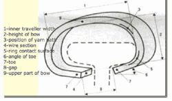
The traveller
- The traveller imparts twist to the yarn
- It enables winding of the yarn on the cop
- Its speed is somewhat less than that of a spindle
- The traveller does not have a drive of its own but is dragged along behind the spindle
![Traveler types]()

The traveller mass
The traveller mass determines the winding and the balloon tension. If the traveller is too small the balloon will be too big and the cop too soft, material take-up in the cop will be too low. An unduly high traveller mass leads to high yarn tensions and many end breaks.


Very Informative blog.
Thanks!!