
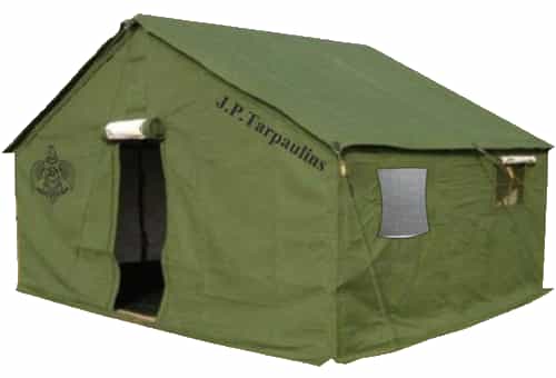
Part-1 of the article on Vinyl Tarpaulin Fabric properties and application
Raw materials
Polyester filament yarns for Tarpaulin woven fabric
Warp yarns
High tenacity (HT) multifilament’s, twisted two ply or high intermingled polyester yarn, denier per filament (dpf). Ideally and in general, DPF should be 5.2 e.g. 1000 denier / 192 Filaments.
Weft yarns
High tenacity (HT) multifilament’s, No or low intermingled polyester yarn, denier per filament (dpf). Ideally and in general, DPF should be 5.2 e.g. 1000 denier / 192 Filaments.
For warp and weft yarns
A filament is a single thread-like object. Multifilament implies there is more than one filament. Fil count tells us how many single filaments there are in the cross-section making up the total Denier. An important parameter to consider is denier per filament (dpf). Ideally and in general, DPF should be 5.2 e.g. 1000 denier / 192 Filaments. Lower dpf offer a softer feel at standard twist levels, while higher dpf may offer better resistance to abrasion.
Yarn made from higher dpf will exhibit higher torque compared to similar denier with a lower dpf. Lower dpf offer a softer feel at standard twist levels, while higher dpf may offer better resistance to abrasion. Yarn made from higher dpf will exhibit higher torque compared to similar denier with a lower dpf. This is used where there is required high tenacity. Or where tenacity has prime role.
For example, Banner, Tarpaulin, Roofing, Membrane Structure, Awning, Filler Fabric, Sunshade, Outdoor Furniture, Hose, Sewing Thread, Seat Belt, Sling, Conveyor Belt Fabric, Geotextile, Rope, Tire Cord, Sail Cloth and so on. The high tenacity yarn has high strength, durability and chemical resistance, and withstands an extremely hot environment that can stress conventional multi-filaments to their performance limits. There is very little variation between the various manufacturers of high tenacity polyester in the general physical properties measured. Other factors including availability, service, spin finish, and package wind quality are often the deciding factor in choosing the best choice for a particular processing application.
The use of filament yarns with a yarn count of 210-750 den and a filament count <5 den (5.5 dtex) is recommended for airbag woven fabrics. The yarns can be untwisted, but a twisted yarn for the warp with a twist of <200 T/m is proposed. In using twisted yarns, the aforementioned disadvantages arise; if an untwisted yarn is employed in the warp, it would be nearly impossible to process it satisfactorily on the loom at a high fabric density without size.
Dyed, Greige—Product Details
Count : Denier:50D, 70D, 100D, 150D, 210D, 250D, 300D, 420D, 500D, 840D
Ply: 2 or 3 plies.
Other Yarn Specifications
- Breaking strength and elongation at break can vary depending on the end use. This is the maximum load that a material can withstand while being stretched or pulled before failing or breaking (also known as tensile strength). Knowing the minimum strength requirement of a finished article is important when deciding what denier to choose as your base material. Very important when failure can lead to liability claims.
- Tenacity is force divided by linear density. The unit of measure is grams/denier. High tenacity is generally preferred over mid tenacity. High strength from finer yarns also offers higher yield with optimum tensile performance.
- Hot air shrinkage is another important consideration of a yarn specification. For example, in hose manufacturing, a yarn is braided around the hose and then put through a vulcanization process and if the yarn does not have correct shrinkage values it can drastically affect the integrity and appearance of the hose after the vulcanization process.
- LOW SHRINK YARN-are used for
- Coating and laminating
- Stator lacing
- Fibre-optic cable binders and ripcords
| High Tenacity (HT) | High Tenacity Low Elongation (HTLE) | Suer High Tenacity (SHT) | Super High Tenacity Low Elongation (SHTLE) | |
|---|---|---|---|---|
| Tenacity (gpd) | 7.6 – 9.2 | 8.5 – 9.8 | 9.3 – 9.8 | 9.0 – 9.8 |
| Shrinkage * | 6.0 – 9.0 | 5.0 – 7.0 | 6.5 – 10.5 | 7.5 – 10.5 |
| Shrinkage ** | 13.0 – 15.0 | 7.0 – 9.0 | 15.0 – 18.0 | 13.0 – 18.0 |
| Elongation @ Break (%) | 12.0 – 16.0 | 11.0 – 15.0 | 10.0 – 16.0 | < 12.0 |
| Mid Shrink (MS) | Low Shrink (LS) | Super Low Shrink (SLS) | High Modulus Low Shrink (HMLS) | High Shrink (HS) | |
|---|---|---|---|---|---|
| Shrinkage * | 3.0 – 5.5 | 0.5 – 2.8 | 0.0 – 2.3 | 2.0 – 4.0 | 7.0 – 12.0 |
| Shrinkage ** | 5.0 – 7.0 | 3.0 – 6.5 | 0.5 – 2.5 | 3.0 – 6.0 | 14.0 – 16.0 |
| Tenacity (gpd) | 7.5 – 8.1 | 7.5 – 8.6 | 7.7 – 8.6 | 7.7 – 8.1 | >= 8.7 |
| Elongation @ Break (%) | 12.0 – 22.0 | 11.5 – 25.0 | 11.0 – 28.0 | 10.0 – 14.0 | 13.0 – 17.0 |
Warping
Warping Process in Weaving: Objectives, Types, Operation and Problems
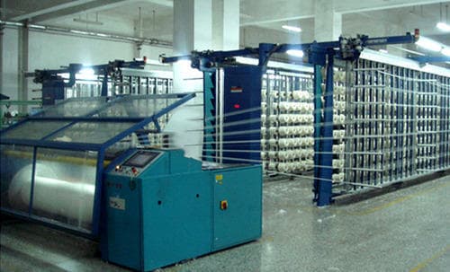
The main objective of warping is to prepare a warp sheet of desired planned length containing the desired number of yarns that are wrapped on a flanged barrel in such a manner that tension in each yarn and density of yarn mass in the cylindrical assembly is maintained within a given tolerance level throughout the wrapping of the warp beam. By warping process yarn quality increase, wound up the fixed length of yarn on weaver’s beam. Increase the wearability of yarn. In this process, small packages can be re-use. After all, increase the production. The process of warping is dedicated to the conversion of cones into a beam of given specifications.
Types of Warping
There are two types of warping that are popular in the textile industry for preparing warp yarn for power-driven high-speed looms or handlooms. These are:
- Direct Warping or Beam warping
- Sectional Warping
Direct Warping or Beam warping:
When the yarns are drawn from the single packages on the creel directly onto the beam then it is called direct warping. It is also called high-speed warping or beam warping. Direct warping is used to make smaller beams which are combined later in slashing to produce the weaver’s beam. Direct warping is used to manufacture different types of fabrics for various applications; that will be dyed or fully bleached during wet processing. Modern beam warping machines have creels with moveable trolleys. The trolleys are movable so that cones can be creeled in reserve when one set is working in the machine.
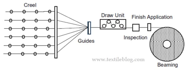
A process in which a number of thread lines, usually 800 to 2000 ends of POY feedstock, are oriented under essentially equal mechanical & thermal conditions by a stretching stage using variable speed rolls, then directly wound onto the beam. Draw warping process gives uniform end-to-end properties.
Sectional Warping
When the yarns are wound onto the beam in sections starting with the tapered end of the beam then it is called sectional warping. Sectional warping is used for the weaving of industrial/technical and conventual fabrics/towels containing stripes or without stripes. Multiple colours of yarn can be incorporated into the weaver’s beam by using sectional warping. The drum of the beam has a cone that has a slight angle that will prevent the yarns from slipping off.
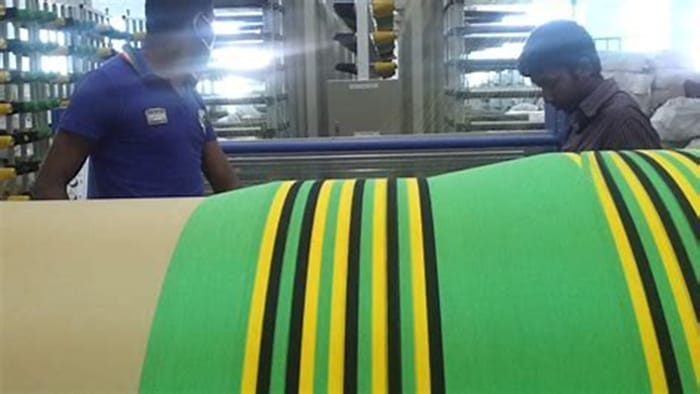
Sectional Warping Procedure
The warping process is one of the weaving preparations processes to produce weaver’s beams which uses on weaving machines with or without sizing as per the requirement to produce grey fabrics. In sectional warping, several hundreds of yarns from supply packages placed on a creel are wound onto a sectional warping drum as sections and then beaming off all warp yarns from the drum to the warper’s beam, which is used for fabric production with or without the subsequent process known as sizing.
The uniform and even yarn tension in the warping process is vital to produce high-quality fabrics on looms with high efficiency. The professionals attempted to theoretically interpret in terms of mathematical modelling the warp yarn tension in the yarn path of the creel with due consideration to various parameters in sectional warping. Further, theoretically model the warp tension variation according to the geometrical position of the package on a sectional warping creel.
The study on tension variation of synthetic/natural yarn unwinding from the supply package up to the exit point of the creel of the sectional warping machine. The mathematical model can be developed to analyze tension variation within the warping creel for the packages with variable diameters at different positions. Based on the developed mathematical model, tension can be calculated at various places along the yarn path
Sketch of a Yarn path through two-zone tension device Few researchers calculated the tension variation of yarn at the tension devices experimentally and analytically.
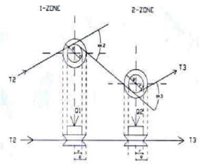
INDIRECT WARPING OR SECTIONAL WARPING
In this method of warping, the warp ends are first wrapped on the warping drum and then transferred on the weaver’s beam. This warping method is mostly used for the warping of 2 plies twisted multiplies yarn, multicolour warp, continuous filament yarns. The single-ply can also be used in this machine. Since the warp ends are wrapped over the drum in no. of sections, so that warping with less no. of warp packages is possible in this method. This method becomes more useful when the required warp length is very low.
STRUCTURE AND WORKING PRINCIPLE OF INDIRECT OR SECTIONAL WARPING MACHINE
CREEL
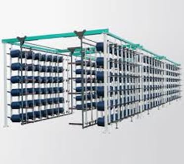 The yarn packages are mounted on the creel. It is a very important part of the warping machine. Creel is a frame of round or square section pipes and iron channels. The cone holders are arranged in vertical columns on both sides of the creel 50 columns of cone holders on both sides of the creel are there in the creel of the sectional warping machine. The creel of sectional warping contains 8 rows on each side.
The number of columns varies according to the requirement of creel capacity. In this creel, yarn packages are mounted on the cone holders from outside of the creel. After loading the yarn packages on the creel, the stands of creel are revolved at 180 degrees. A yarn guide and a tensioner are provided in the creel for each warp end. These are mounted on the iron frame which can move away by rotating handwheel or electric motor. The yarn coming from the package first of all passes through the ceramic yarn guide then it passes through the yarn tensioner.
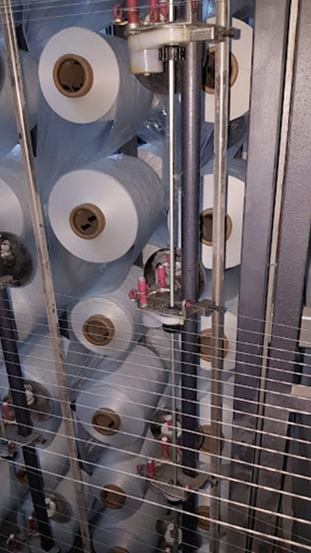
The main function of the tensioner fitted with an inverted cup and deadweight washers is to impart a sufficient amount of tension to the yarn. The number of washers and their weight depends upon the yarn count to be used in the warping process and accordingly number of washers are reduced or increased manually. In automatic creel, the tension of all tensioners is reduced or increased by a mechanism, which is operated by an electric motor.
The warp end passes through many ceramic guides which are arranged at equal distance to each other. The distance depends upon the length of the creel. The main objective of these guides is to keep separate each end and to prevent an end-to-end entanglement during warping.
The second objective of these guides is to provide enough support to each end. Now the next passage of warp end is drop wire. Its objective is to stop the machine immediately when end breakage occurs. The creel is equipped with fully automatic warp stop motion. The indication lamps on each row are provided in the creel whenever ends breakage occurs the indication lamp puts on immediately and the machine is stopped. These indication lamps help the operator to identify the correct situation broken end in the creel.
SEPARATING RODS
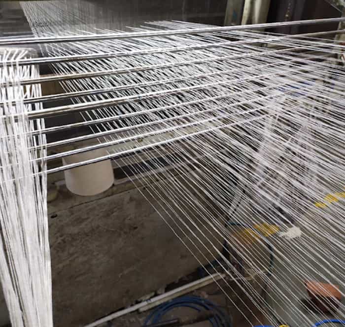
The ends coming out from the drop wire passes between the separator rods as per plan.
Leese reed
A separator rod helps to prevent the warp ends to be entangled to each other and makes the smooth movement of ends during operation. It plays a very important role in the warping of multicolour warp of single-ply yarn which necessitates sizing. The warp separation leases are inserted with the help of these separator rods.
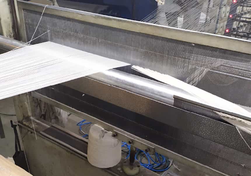
It is located just after the separator rods. Its function is to help to insert the lease (the lease contains two strings). All the odd number ends pass over the first string and even number ends pass under it. Now odd number ends change their position and pass under the second string. The even number ends also change their position too and pass over the second string).
This reed is design in such a way that the warp ends are divided into two layers when it is lowered or lifted. A pneumatic cylinder is used to lift or lower it. In some machines toothed racks, gears and electric motor
The yarn now passes through the dents of flat or v – shape reed. The main role of it is to keep the warp ends parallel to each other. It also maintains equal space among all warp ends. The number of ends per inch in the weaver’s beam depends upon the reed count and denting order used.
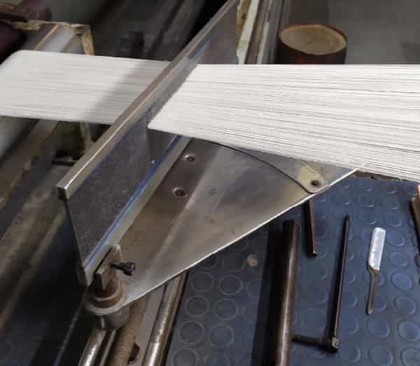
This reed is mounted on the reed table which can move left and right direction by rotating a hand wheel fitted at one side of the table. Reed can also be turned at a certain angle for adjusting section width whenever flat reed is being used. When the v-shape reed is used, the adjusting table has the mechanism to reduce or increase the width of the reed.
GUIDE ROLLERS
The warp ends now pass between two guide rollers. These rollers are made of stainless steel, Teflon or vacalite fibre sheet. Lengthwise grooves are made on these rollers which help to spread the warp end in the section.
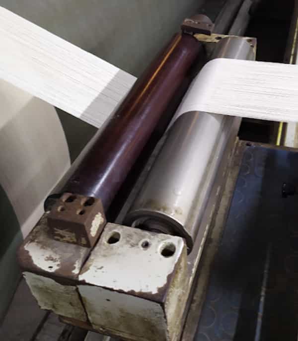
These rollers are not driven positively. Yarn tension helps to rotate these rollers.
WARPING DRUM
This is a metallic drum. Its diameter varies from 2.5 to 3.0 metres according to the make of the machine. The length of the drum varies according to the maximum beam width required to be warped. The one side of the drum is designed in a conical shape. The cone length varies from 1100 – 1200 mm.
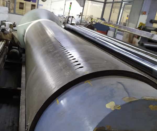
The surface of the conical portion of the drum is made rough to prevent slippage of yarn during warping. The drum rotates by electric motor in a clockwise direction during the warping process.
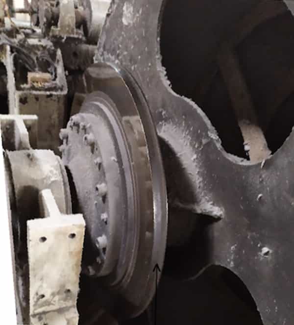
HYDRAULIC DRUM BRAKES
The main function of the brake in the warping machine is to break the momentum of the drum rotating at high speed in case of machine stoppages. Two types of brakes are used in the machine. In the drum brake system, the brake drum is mounted on the shaft of the warping drum. It rotates with a warping drum. A brake belt rests on the brake drum. One end of the belt is fixed and another end is connected to the hydraulically operated arm.
When the machine stops, the arm pulls the brake belt and exerts pressure on the brake drum. Thus, the machine stops immediately. This braking system also provides tension to warp during the beaming process. in the disc brake system, two brake discs are mounted on the drum shaft at each side of the drum. Brake shoes are also fitted on each disc. These shoes are operated hydraulically.
When the machine stops, brake shoes act immediately and grip the disc. Thus, the machine stops immediately. It also provides tension during the beaming process.
DRUMTRAVERSINGMOTION
The whole machine is mounted over the traverse rail. Four wheels are provided in the machine which makes the machine movable in the left and right directions. A gearing system and electric motor are used to perform traverse motion to the drum. When the yarn is wound over the cone drum, the drum moves in the left direction gradually to achieve the conical shape of the section.
A square threaded shaft rotates through gearing and an electric motor with a drum. This shaft carries the drum in the left direction during warping. An electronic encoder is fitted at the one end of this threaded shaft which counts the rotation of the shaft from the starting of the section till the end of the section. When the section is completed, the machine moves in the left direction by pressing a reset push button. The machine travels the distance equal to the distance travelled in the right direction plus the distance equal to the section width.
WAXING
It is an optional device but very useful to improve the quality of warp yarn during the process. It is located between the warping drum and the beaming system. In this device, three rollers are used. A steel trey is used to fill the chemical to be applied to the yarn. The middle roller is mounted over the trey.
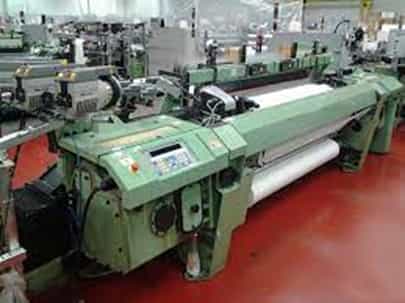
Nearly half portion of the middle roller immerses in the trey. The other two rollers guide the warp yarn only. A chain sprocket is mounted at the one end of a middle roller which receives the rotational motion through the electric motor. The speed of the middle roller is controlled by an A.C. drive. When any liquid chemical is applied to the warp, the liquid is filled in the chemical tray.
The middle roller rotating in the opposite direction of yarn touches the surface of the warp. The surface of the roller lifts the liquid and applies it to the yarn surface. The amount of chemical to be applied is regulated by adjusting the speed of the middle roller.
BEAMING SYSTEM
When the warping is completed, there is needed to transfer the warp on the weaver’s beam. This transfer of warp from drum to weaver’s beam is called the beaming process. The beaming system mainly consists of beam loading arrangement and beam traversing arrangement and beam drive mechanism. The empty beam is mounted on the beaming system by means of a loading system. An iron frame on each side of the machine slides over the slide rail. These frames are moved left and right direction with the help of a square threaded shaft fitted across the width of the machine. When this shaft rotates in the threaded brackets attached with the iron frames, it carries the iron frames left and right direction. The left side frame can be moved also by a hand wheel which moves on the toothed rack with the help of gear.
The adapters mounted on each side of the beam are entered in the hollow shafts. These shafts can be lifted or lowered according to requirement by hydraulic pressure. The hollow shaft of the left rotates freely but the right-side shaft has a positive drive. This shaft rotates the beam during beaming. This shaft receives the rotational motion through an electric motor and a reduction gearbox. This shaft is connected to the gearbox through a universal joint which maintains the alignment automatically during lifting and lowering the beam.
FULL WARP LENGTH STOP MOTION
It is a fully electronically controlled system. A shaft encoder is mounted on the shaft of the warping drum which counted the rotations of the warping drum. A control panel converts the rotations of the drum into length in metres automatically. When warp length reaches completion, the machine stops automatically before few metres of warp length. Now machine comes in slow-speed mode and completes the wrapping of the remaining warp length and becomes stationary. This system is more useful during chances of brake failure.
MULTI LEASE STOP MOTION
This is digitally controlled motion. This motion helps to insert more than one lease (multi leases) in one warp beam. Suppose we have to make three small warp beams say 600 metres. Length of each beam. During warping, we make a beam of 1800 metres. We insert leases at the beginning and after every 600 metres of warp length. When we start the machine after insertion of the initial lease, the machine stops automatically after wrapping 600 metres of warp.
Now the second lease is inserted and the machine is started again. Now machine again stops after 600 metres of wrapping of warp. The operator inserts the third and final lease in the warp and starts the machine again. During beaming, these three warp beams are separated. Thus, every beam has an individual lease in it and time-saving occurs in the process.
 HYDRAULIC PRESSURE SYSTEM
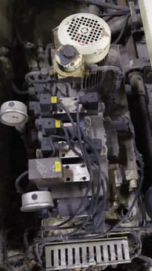
A hydraulic pressure device is used to generate pressure to bring up and down the beam, pressure also imparts tension to the warp during beaming. Hydraulic pressure controls the compactness of the beam. Hydraulic pressure breaks the momentum of the rotating drum in case of machine stoppages.
Generally, a cuboid shape oil tank is used which is located at one side of the machine. 68 no. hydraulic oil is filled in this tank. A geared oil pump is mounted on this oil tank. The inlet of the oil pump rests in the oil. The oil enters the oil pump through an oil filter which does filter the oil. The pump’s shaft is connected to the electric motor.
This motor rotates the oil pump. The outlet of the oil pump is connected to the pressure distribution arrangement. This distribution arrangement has magnetic valves, pressure regulators and oil pipes. The magnetic valves help to make oil supply on and off in various points according to requirement. The pressure is varied by using a regulator during beaming.
A pressure meter is used to read the actual value of pressure. Push buttons are used to lift or lower the beam. This is an integrated A.C. inverter drive. This drive operates three electric motors (warping motor, beaming motor and machine traversing motor). The speed of warping and beaming is controlled by this drive. During the warping process, the required warping speed is entered into the monitor. During the beaming process, the required speed is increased or decreased by using a pot in the machine.
PRECAUTIONS DURING SECTIONAL WARPING MACHINE
Following precautions must be taken during the sectional warping process:
- The tension on each warp end should be equal and sufficient.
- The creel should be cleaned with compressed air after every creel change.
- The package size should be equal. The size difference in packages creates uneven tension on the ends.
- The distance between the package and yarn guide should be proper and sufficient to prevent balloon formation during the unwinding of yarn from a package.
- The effective working of electrical stop motion should always be ensured.
- The distance between stop motion and lease reed should sufficient. If it is too low, it may cause unnecessary end breakages. If this distance is too high, it may cause excessive short end in the warp and entanglement of ends which results in form of end breakages.
- The distance between lease reed and flat reed or v – shape reed should be correct to minimize the end breakages at the reed.
- Gears selection should be as accurate as possible. Incorrect gears selection results in the improper cone height of the warp beam thus the diameter of the beam at one side reduces or increases. This variation in diameter results in form of bowing in fabric.
- The warping speed should not be changed during the process, speed change during the process may change the length of section or tension of the warp.
- All the sections should have an equal number of ends if possible.
- Section width should be set correctly. If section width is less than required, there will be gap between adjacent sections and warp will become loose at these places. If it is more than required, the ends will be overlapped and it will create end breakage during beaming.
- There should not go any short end in the beam during warp. Short end crates lappers and end breakage during beaming.
- Every short end should be repaired by reversing the machine in the back direction.
- Efficient working should be ensured before operating the machine.
- The oil level in the hydraulic system is maintained properly.
- The discs and brake shoe of the braking system should be cleaned by CTC or another solvent.
- Wax, cold binder or antistatic oil should be used if required.
- Beaming tension should be selected properly. The beam should be neither much compact nor much loose.
- Excess beaming tension may create deformation in the yarn.
- The flange-to-flange distance in the beam should be set correctly.
- The beam width should be two centimetres more than the reed space used in the loom.
- The warp should be wound on the beam in the centre of the barrel.
- The flanges should be tightened properly.
- The lease should be inserted correctly to prevent the end crossing problem.
- The number of ends per dent in the flat or v – shape reed should be as minimum as possible. The excess number of ends per dent in this reed results in the form of rolling. This rolling creates an end crossing problem during the unwinding of the warp on the loom.
- Proper working of the machine should be ensured by the empty running of the machine.
- The electrodes of warp stop motion should be cleaned periodically.
- The roughness of the surface of a cone-shaped portion of the warping drum should be maintained properly. If it becomes smooth, the slippage of sections on this side may occur.
KNOTTING PROCESS
Tying (knotting) or piecing
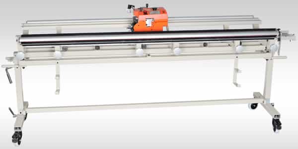
When the fabric design is repeated on the same loom after the weaver’s beam exhaustion, there is no need to perform the drawing-in process on that loom. The tying process is used to replace the exhausted weaver’s beam with a new weaver’s beam. Tying or knotting is the process of joining the ends of an exhausted weaver’s beam with the ends of the new weaver’s beam. It is performed manually or mechanically. When it is performed manually, it is called “piecing”. When it is performed mechanically, it is called “knotting”.
Knotting activities
- Unloading the beam
- Loading in new beam – The unload exhausted warp beam in loom and cleaning, oiling of the loom. Therefore load the new warp beam in the loom.
- Set the knotting frame – After loading the new warp beam are loading the warp knotting frame in parallel to loom
- Fix the brush and clamp
- Pull the ends
- Dressing the end with help of a comb brush – After frame loading, the dressing of the beam should be done properly to avoid cross end in new & old warp sheets. To minimize the incidence of cross end on the beam during weaving, the end presented for drawing-in or warp tying should be made to be parallel and in their respective positions as in the beam. Proper dressing of the end is, therefore of great importance. The task of dressing can be made easy and the end maintained in a parallel position by pasting a gum tape across the width of the weaver beam, which is about to be doffed from the sectional warping/size machine. The tape should be put a few inches above the line of cutting the end.
- Fix the end in the knotting frame (with clamp)
- Pull the end from the beam
- Dressing the end with the use of comb & brush
- Fix the clamp on the end
- Set the Knotter on stand
- Start the warp knotting operation– After completion of dressing of warp sheet process are tying the new warp sheet and old warp sheet. The tying of warp sheet end to end tying
- After completion of knotting it’s passing through the reed—The various setting required for as per the sort After compilation of frame unloading the next process is passing the knot in drop-in, heald wire and reed for manually running for the loom.
The WARPMATIC warp tying or warp knitting machine is a highly advanced machine designed for universal use in warp change to install new beams produced on warping machines. Targeted at improving labour efficiency & productivity, it is quick to set up, easy to operate, and reliably ties a wide range of standard yarns.
Special features allow tying of single knots, double knots, or both. Additionally, repeat programming allows tying of coloured warps. The display shows ideal operating parameters including a number of knots completed. A special preventive feature ensures that the machine stops in case of 3 ineffective knots.
Application
During Warp change, the WARPMATIC can automatically tie warp ends of the existing beam with a new beam produced on the warping machine. This Warp knotting machine eliminates the requirement of specially skilled workers & provides error-free warp change.
Technology
- Maximum speeds of up to 600 knots/minute
- Precision BLDC motors emit low noise
- LCD line display shows the number of knots
- Automatically stops working in case of 3 failed knots
- Freely adjust knots of Warp with different patterns
Highlights
Productivity
- Quick & Easy warp preparation on the tying frame
- Reliable knot formation even at high tying speed
- Perfect drawing of warp threads through the weaving harness
Flexibility
- A wide range of staple fibres and filament yarns can be tied with minimal adjustments.
- Can deliver single or double knots quickly & easily as per demands of warp yarn.
- Suitable for warps with or without a regular or irregular lease in upper or lower sheet, single or multi-colour, depending on yarn types.
Quality
- The smart detection system of WARPMATIC can identify double threads operating in warps with or without a lease
- Reduction in double threads & redirected warp threads enable high efficiency & productivity of the weaving machine.
DRAWING – IN PROCESS, A WEAVING PROCESS
DRAWING-IN PROCESS
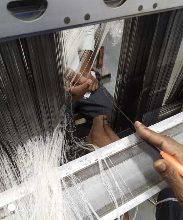
“A process of passing the end through the eye of heald wire or harness according to the draft (sequence of drafting the ends) is called drafting”. When the drafting is performed manually, two persons do this job. The person who selects the ends and presents them for drawing is called the reacher. The person who draws the ends through the eye of heald wire with the help of a drawing hook is called a drawer.
The drawing-in process comes just after the preparation of the weaver’s beam. The weaver’s beam is obtained from sectional warping or sizing. The drawing-in process mainly consists of two processes. The first process is called drafting and the second process is called denting. It is mostly performed manually but in large scale textile industries, automatic drawing-in machines are used, where more productivity is required. When the drop wires with closed D are used, the ends are drawn through as per the drafting plan to the drop wires before the heald eye.
The drawing-in process is applied for the execution of a new fabric design on the loom. When the fabric design is repeated regularly, the warp tying (knotting) process is applied to change a weaver’s beam. The tying process is done manually or with the help of a knitting machine.
METHOD OF DRAFTING
There are two methods of drafting which are given below:
- Manual drafting method
- Automatic drafting method
Manual or hand drafting method
This method is performed manually. It is a too time-consuming process in the drawing-in process. Highly skilled persons are needed to perform this task. The required number of heald shafts are prepared. The heald wires are inserted into each heald shaft according to the total number of ends present in the weaver’s beam. These heald shafts are hanged on the stand. Now weaver’s beam is put just behind the stand. Each end of the barrel of the weaver’s beam rests on the two bearings fitted on the small iron stand. These bearing stands helps to rotate the weaver’s beam in any direction.
Now the warp sheet passes over the aluminium pipe fitted across the full width of the drawing stand. If the beam is prepared on the sectional warping machine, it has ended the separation lease. The reacher clears the ends with the help of a dressing brush. If sized weaver’s beam is used, there is needed to fix the ends on their place with the help of half reed of suitable count. Before hanging the warp on the aluminium pipe, one or two layers of the wrap sheet are unwound. Now the ends of the warp sheet are fixed with the help of gum tape.
The half-metre length of the warp sheet is unwound again and another gum tape is put. Now half reed is inserted in the warp sheet between the two gum tapes fixed earlier on the warp sheet. This half reed is tied with the drawing stand. This half reed prevents changing the position ends in the warp sheet and end crossing in the sheet. Now the reacher selects the end according to lease or half reed and presents it in front of the eye of the heald wire selected by the drawer. The drawer inserts the drawing hook into the eye of the heald wire and the reacher puts the selected end in the hook.
When the drawer pulls the hook, the end also comes with a drawing hook, thus the end is drawn through the eye of heald wire. This action is repeated again and again till completion of drafting of full warp sheet. When the drafting is completed, the ends are passed through dents of reed. When one person does this process, he first selects the end, then inserts the denting stipe into the dent, then put the selected end into the slot of denting stripe. Now he grips the stripe with the help of left hand under the reed and pulls the stripe. Thus end is passed through the dent of reed. This action is repeated till the completion of denting of the full warp beam.
METHOD OF DRAFTING
There are two methods of drafting which are given below:
- Manual drafting method
- Automatic drafting method
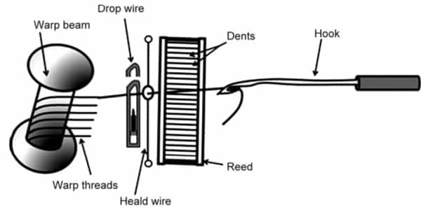
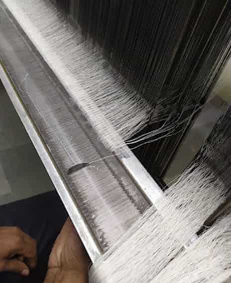
Denting in reed– Denting means drawing the warp thread through the dent as required by the reed plan and this determines more accurately the width of the fabric and the ends per cm/inch.
Reed: The reed is a comb-like structure consisting of regularly spaced wires. The word dent is commonly used to describe the space between two reed wires.
Suitability of different weaving machines to weave tarpaulin fabric.
To develop and design the fabric especially for Tarpaulins Porosity/air permeability are properties required. The ratio of the total amount of void space in a material to the bulk volume occupied by the material. Fabric porosity is an important parameter in the assessment of clothing comfort and the physical properties of technical textiles. This brief reports the influence of constructional parameters of a woven fabric, such as yarn linear density, type of weave, and relative fabric density on the macropore area and its distribution.
Predictive models of macropore area and macropore area distribution have been developed for engineering one-layer woven fabrics. The production of modern woven fabrics demands developing strategies considering new structures. It is clear that a new fabric structure should have the desired quality at minimum production costs, and the highest possible weaving efficiency. Achieving such a demand is a complex task based on our knowledge of the connections between woven fabric structure parameters and the predetermined fabric properties that fit the desired quality. The evolution of ‘maximum construction theories’, as well as the fast development of computer science, allows us faster and more precise planning of new products.
In the field of ‘maximum construction theories,’ some relationships are well known, which can, in the form of computer programs, serve as a part of an expert system for the development of new fabrics. However, in the field of connections between the woven fabric structure and the individual fabric properties, such as example porosity, a need arises further to determine some of such relationships; firstly, should be developed a ‘maximum construction theory’ about square fabrics using simple geometry. Gee introduced the well-known ‘ends plus intersection theory’, which he upgraded, and named the ‘curvature theory’ [1]. Until then a ‘maximum theory’ had been the subject of several research.
Some researchers, such as Peirce, Love, Kemp, Hamilton, Weiner, Peirce & Womersley [2], Love, Kemp, Hamilton, and Weiner [3, 4, 5, 6] have used a more theoretical approach, whereas some other as Armitage, Law, Brierley, Seyam & El-Shiekh (1993), Gee (1953), and Brierley [7] used more experimental means. M. Kienbaum [8] has successfully joined theoretical and experimental investigations and presented his own theory which can be applied to all weaves and different yarn structures.
I suggest all readers read my article on the Importance of shed geometry on the operational performance of Weaving machines. This is a technical article suitable to match all makes of weaving machines. This is written exclusively for weaving machine settings.
Projectile weaving machines
These machines are mainly used for spun yarns made of cotton, rayon, polyester, etc and also their blends. It is also possible to effectively weave filament yarns. The technical aspects relating to warp yarns remain the same irrespective of whether it is shuttleless or shuttle looms. Some of the recommended weft yarn counts are given in Table1 below.
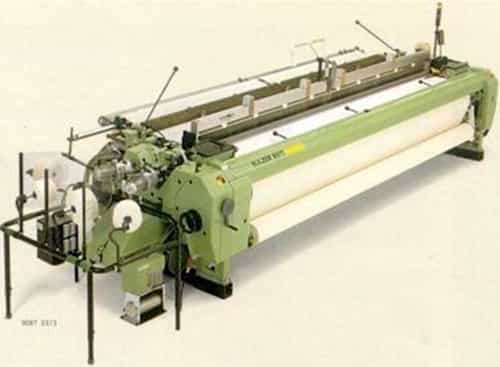
These machines can satisfactorily weave sheeting, flannels, drills, muslins, print cloths, etc and it can be extended to the weaving of carpets from continuous filament yarns. Textured filaments made from Taslan, untwisted filament and intermingled cotton and polyester covered core yarns and elastomeric yarns can be effectively woven on these machines. Heavy denier multifilament yarns can also be successfully used. PET with crepe twist or reinforced Lurex is both woven as weft without problems. Industrial fabrics, tyrecords, tents, screens, sailcloth tarpaulin, and glass fabric can also be woven
Air-jet weaving machine
These machines have proved to be ideal for spun yarns. Recently it has been possible to weave a wider range of fabrics in spun as well as filament yarns and with up to six colours in weft or yarn counts. However, the yarn quality restricts the machine speed. Modem spinning mills are able to give better quality yarns. Modem warp preparation is crucial for today’s weaving machines.
Water-jet weaving machine
This system has proved very useful in the case of synthetic filament yarns, which are hydrophobic. It is advantageous as compared with shuttle looms for bulk production of fabrics made of polyamides and other hydrophobic fibres. This machine is confined to only hydrophobic synthetic filament yarns. This is due to the problems associated with sizing, the wet strength of hydrophilic yarns and also the requirement of a perfectly clear warp shed. Thus the machine is restricted to filament warp yarns that do not require sizing and also do not lose strength on wetting.
Normally weaves such as crepe, matt, and twill are used, with yarn counts ranging between 10 – 120 denier. The warp/weft thread sett or density ranges between 25/25 and 360/240 per square inch and the maximum achievable areal density of the fabric is about 6 0zlsq yd. Since the construction of the weaving machine, especially, the sley is light, heavier varieties of fabrics cannot be woven. There is a possibility to increase the weft set to 300 picks/inch.
However, the maximum dents/inch in reed is only 76. If reeds of higher densities are used, there is a problem of water clogging, which can create difficulties in shedding. The twist in warp yarns is minimum, about 7.5 TPI, as the yarn is unsized. Fabrics such as lingerie, ladies dresses, shirting, tent canvas and industrial fabrics can be successfully woven on these machines. The overall quality of the fabric is below the expected level, which is mainly due to the problems concerned with the water jet weft insertion.
These machines have the advantages of high speed and low noise. Also, they are well suited for weaving superfine continuous filament yarns. The effectiveness of the weft propulsion is mainly dependent on the wettability of the weft. The drag on hydrophobic filament yarn is much lesser than that on cotton yarns. Generation of static charges is prevented due to the presence of water. It is crucial that the weft yarns do not contact the warp yarns during their insertion into the shed, as otherwise, this could lead to fabric defects due to entanglement.
The effectiveness of weft insertion requires the fluid jet to remain in contact with the weft and to move into the shed more quickly than the yarn. A major problem with hydraulic picking is the presence of partial full double picks across the width of the fabric, which can arise due to a number of reasons.
Weaving with multifilament yarns
Multifilament yarns are used in the manufacture of apparel so as to get an excellent hand, drape, appearance, wrinkle resistance and easy-care properties. The yarns are either used as single or plied together with or without twists. The yarns are denoted as denier/number of constituent filaments/twist. Generally higher the number of filaments of equal denier, fuller is the fabric. The yarns can be woven successfully on any of the following types of machines (Table 2) but certain modifications on looms are required for satisfactory weaving. It is desirable to weave the filament warp beams on better and sophisticated looms.
| Type of weaving machine | Products |
| Projectile/Rapier | • Fancy multicolor fabrics coarser than 30 dTex, both flat and texturized
• High twisted fabrics |
| Air-jet | • Fabric with single color weft for mass production |
| High speed automatic shuttle looms, conventional automatic looms | • Fancy monocular fabrics
• High twist fabrics |
| Non-automatic looms | • All type of synthetic fabrics |
Recommended Warp Count
| Warp count dTex | Cross-section of Heald mm x mm | Sizes of eyes mm x mm | Maximum Simplex | Heald wire per cm Duplex |
|---|---|---|---|---|
| Upto 150 | 1.0 x 0.25 | 5.0 x 1.0 | 16 | 24 |
| 140 to 300 | 2.0 x 3.0 | 5.5 x 1.2 | 12 | 20 |
Tarpaulin Fabric : 280g-800g/sqm, PVC tarpaulin, 200D*300D,250D,500D(18*17) 1000D(20*20), truck cover,awning,tent,etc
Part-1 of the article on Vinyl Tarpaulin Fabric properties and application
Conclusion
This study was conducted to identify the relationships between increase in market share through product development and innovation. Many studies have been done on the concept of product development and innovation and much of what has been written tends to discuss this concept as a veritable tool for improving the life cycle of a product without substantial relation to market share enhancement.
The invention provides a manufacture method of water-proof sailcloth, which solves the problems of the prior art that manual work cost and management cost are added by large area occupied by creels. From the survey it can be concluded that there is huge demand of vinyl tarpaulins in local and international market. Companies can enter in to the market with best features, best pricing policy and best promotion tools.


sulzer weaving (P7100)machine maintenance cost /year
Sure madam. thanks you have liked my article.
I want learnt how to make batik
Its an awesome article stating about textile mill, I like how you have researched and presented these exact points so clearly, Im Also working in Sapphire Textile Mills Karachi Pakistan. U Can Vist My Website
http://sapphiretextiles .com.pk/